Example: Configuring Link Aggregation in Manual Load Balancing Mode
Networking Requirements
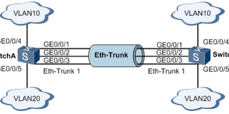
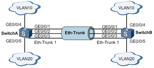
As shown in Figure 1, SwitchA and SwitchB are each connected to VLAN 10 and VLAN 20 networks through Ethernet links, and a large volume of data traffic is exchanged between SwitchA and SwitchB.
The user wants to provide greater link bandwidth between SwitchA and SwitchB so that devices in the same VLAN can communicate with each other. The user also wants a certain degree of redundancy to ensure the reliability of data transmission and links.
Figure 1 Networking diagram for configuring link aggregation in manual load balancing mode
Configuration Roadmap
Configure load balancing link aggregation as follows:
Create an Eth-Trunk interface and add member interfaces to it to increase link bandwidth.
NOTE:
By default, interfaces are added to VLAN 1. Therefore, before adding an interface to an Eth-Trunk, it is recommended that you remove the interface from VLAN 1 or shut down the interface to prevent broadcast storms.
Create VLANs and add interfaces to the VLANs.
Configure the load balancing mode so that traffic is load balanced among the member interfaces of the Eth-Trunk, improving reliability.
Procedure
Create an Eth-Trunk interface on SwitchA and add member interfaces to it. The configuration on SwitchB is similar to that on SwitchA and is not described here.
<HUAWEI> system-view
[HUAWEI] sysname SwitchA
[SwitchA] interface eth-trunk 1
[SwitchA-Eth-Trunk1] trunkport gigabitethernet 0/0/1 to 0/0/3
[SwitchA-Eth-Trunk1] quit
Create VLANs and add interfaces to the VLANs. The configuration on SwitchB is similar to that on SwitchA and is not described here.
# Create VLAN 10 and VLAN 20 and add interfaces to them.
[SwitchA] vlan batch 10 20
[SwitchA] interface gigabitethernet 0/0/4
[SwitchA-GigabitEthernet0/0/4] port link-type trunk
[SwitchA-GigabitEthernet0/0/4] port trunk allow-pass vlan 10
[SwitchA-GigabitEthernet0/0/4] quit
[SwitchA] interface gigabitethernet 0/0/5
[SwitchA-GigabitEthernet0/0/5] port link-type trunk
[SwitchA-GigabitEthernet0/0/5] port trunk allow-pass vlan 20
[SwitchA-GigabitEthernet0/0/5] quit
# Configure Eth-Trunk 1 to allow VLAN 10 and VLAN 20 to pass through.
[SwitchA] interface eth-trunk 1
[SwitchA-Eth-Trunk1] port link-type trunk
[SwitchA-Eth-Trunk1] port trunk allow-pass vlan 10 20
Configure the load balancing mode for Eth-Trunk 1. The configuration on SwitchB is similar to that on SwitchA and is not described here.
[SwitchA-Eth-Trunk1] load-balance src-dst-mac
[SwitchA-Eth-Trunk1] quit
Example: Configuring Link Aggregation in LACP Mode
Networking Requirements
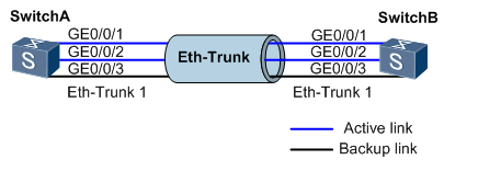
As shown in Figure 1, configure a link aggregation group in LACP mode on two switches to increase the bandwidth and reliability between the two devices. The requirements are as follows:
The two active links must be able to load balance traffic.
One redundant backup link must be available between the two devices. When an active link fails, the backup link takes over from the faulty link to maintain reliable data transmission.
Figure 1 Networking diagram for configuring link aggregation in LACP mode
Configuration Roadmap
Configure LACP mode link aggregation as follows:
Create an Eth-Trunk and set it to work in LACP mode to implement link aggregation.
Add member interfaces to the Eth-Trunk.
NOTE:
By default, interfaces are added to VLAN 1. Therefore, before adding an interface to an Eth-Trunk, it is recommended that you remove the interface from VLAN 1 or shut down the interface to prevent broadcast storms.
Configure the system priority to determine the actor, and select active interfaces based on the interfaces on the actor device.
Configure the upper threshold for the number of active interfaces to improve network reliability while guaranteeing bandwidth.
Configure interface priorities to determine the active link interfaces. The interface with the higher priority is selected as an active interface.
Procedure
Create Eth-Trunk 1 on SwitchA and set it to LACP mode. The configuration process on SwitchB is similar to that on SwitchA and is not described here.
<HUAWEI> system-view
[HUAWEI] sysname SwitchA
[SwitchA] interface eth-trunk 1
[SwitchA-Eth-Trunk1] mode lacp
[SwitchA-Eth-Trunk1] quit
Add the member interfaces on SwitchA to the Eth-Trunk. The configuration process on SwitchB is similar to that on SwitchA and is not described here.
[SwitchA] interface gigabitethernet 0/0/1
[SwitchA-GigabitEthernet0/0/1] eth-trunk 1
[SwitchA-GigabitEthernet0/0/1] quit
[SwitchA] interface gigabitethernet 0/0/2
[SwitchA-GigabitEthernet0/0/2] eth-trunk 1
[SwitchA-GigabitEthernet0/0/2] quit
[SwitchA] interface gigabitethernet 0/0/3
[SwitchA-GigabitEthernet0/0/3] eth-trunk 1
[SwitchA-GigabitEthernet0/0/3] quit
Set the system priority on SwitchA to 100 so that it becomes the LACP actor.
[SwitchA] lacp priority 100
Set the upper threshold for the number of active interfaces on SwitchA to 2.
[SwitchA] interface eth-trunk 1
[SwitchA-Eth-Trunk1] max active-linknumber 2
[SwitchA-Eth-Trunk1] quit
Set interface priorities on SwitchA to determine the active links.
[SwitchA] interface gigabitethernet 0/0/1
[SwitchA-GigabitEthernet0/0/1] lacp priority 100
[SwitchA-GigabitEthernet0/0/1] quit
[SwitchA] interface gigabitethernet 0/0/2
[SwitchA-GigabitEthernet0/0/2] lacp priority 100
[SwitchA-GigabitEthernet0/0/2] quit